Understanding electrical diagrams is crucial for technical students aiming to master troubleshooting and circuit design. The CR-LA60 Aiwa electrical diagram offers an excellent opportunity to study a real-world example of audio equipment circuitry, equipping learners with the knowledge they need for hands-on applications and diagnostics.
This guide will walk you through the CR-LA60 Aiwa electrical diagram, breaking down its components, explaining the circuit design, and exploring its practical applications. By the end, you’ll have a thorough understanding of how the diagram works and how to maintain it effectively.
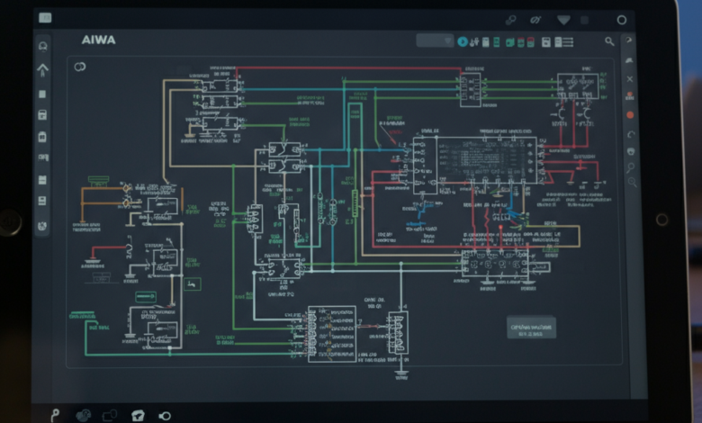
What Is the CR-LA60 Aiwa Electrical Diagram?
The CR-LA60 diagram belongs to Aiwa’s range of iconic cassette decks and stereo audio systems. This electrical schematic outlines the internal circuitry of the CR-LA60 model, which gained popularity in its era for delivering high-quality sound at an affordable price. For technical students, this diagram serves as a roadmap to understanding how signal flows, various components interact, and critical functions like power control and audio signal processing come into play.
By mastering this diagram, you gain insight into not just the CR-LA60 but also the principles that apply to other audio equipment.
Components in the CR-LA60 Aiwa Electrical Diagram
To fully grasp the CR-LA60 Aiwa diagrama electrico, you’ll first need to familiarize yourself with its components. Below are some of the crucial elements you’ll encounter:
1. Power Supply Section
This configuration is responsible for converting alternating current (AC) into the direct current (DC) necessary for the device’s operations. Components to focus on include transformers, diodes, and voltage regulators.
2. Amplification Circuit
Known for delivering clear and powerful audio, the CR-LA60’s amplification circuit uses transistors and capacitors in a clever arrangement to enhance sound signals.
3. Playback Mechanism
Here, you’ll find the motor driver circuit and signal reading components. Key elements include the magnetic tape head, motor control ICs, and mechanisms for playback speed stabilization.
4. Equalization Circuit
A vital part of any cassette deck, the equalizer circuit ensures that the audio frequencies are balanced. This section uses resistors, capacitors, and inductors to equalize low, mid, and high frequencies.
5. Control Buttons and User Interface
Switches, buttons, and indicators present as part of the interface connect through circuit traces back to the control logic chips. They facilitate operations like play, stop, and record.
Diagram Tip!
When studying the diagram, always start with the power supply and progress logically to the output stage. This flow makes it easier to understand how the electricity powers the system and how signals are processed.
Analyzing the Circuit Design and Function
The CR-LA60 Aiwa diagrama electrico showcases a smartly engineered circuit design. Let’s break it down further into major stages of operation:
1. Signal Input and Processing
- Audio input signals are read via the tape head.
- They pass through filters to remove unwanted noise.
- The signal is fed into a preamplifier circuit to prepare for amplification.
2. Signal Amplification
- Once in the main amplification circuit, transistors amplify the signal.
- Feedback mechanisms control gain to prevent distortion.
3. Output Stage
- The amplified signal is sent to the output terminals for speaker connection.
- A tone control circuit adjusts sound according to user preferences.
4. Motor Control for Playback
The motor driver circuit controls the tape mechanism. Sensors embedded in the circuit ensure correct playback speed, critical for maintaining audio fidelity.
Understanding these processes not only deepens your knowledge about audio equipment but also strengthens your ability to troubleshoot when something goes wrong.
Practical Applications of the CR-LA60 Diagram
Studying the CR-LA60 Aiwa electrical diagram pays dividends in practical scenarios. Here’s how it’s helpful:
1. Learn Circuit Debugging
The diagram provides a framework for identifying issues in the circuit. For instance, if the playback motor isn’t working, you can trace the relevant leads and test components like the motor IC or power source.
2. Audio Equipment Repair
Many cassette decks share similar circuit principles. Once you’ve mastered the CR-LA60 internals, you can apply this knowledge to repairing other models.
3. Design Inspiration
Whether you’re designing radio equipment or audio amplifiers, the CR-LA60’s circuit layout inspires creative and efficient designs.
4. Hands-on Learning
Using the CR-LA60 as a learning tool, you can practice soldering, component replacement, or even testing ideas for circuit improvement.
Troubleshooting and Maintenance Tips
Old-school cassette players like the CR-LA60 Aiwa are prone to wear and tear. However, proper troubleshooting ensures they remain functional. Here’s how to approach common issues effectively:
Problem 1: No Power
- What to Check: Inspect the AC plug, transformer, and voltage regulator. Broken traces in the power supply circuit are often the culprit.
Problem 2: Tape Doesn’t Play
- Solution: Check the motor control circuit and clean motor contacts. Dirt accumulation may cause operational delays.
Problem 3: Distorted Audio
- Solution: Inspect the amplification circuit for faulty capacitors or resistors. Adjust tone control components if necessary.
Regular Maintenance Tips
- Always clean the tape head with isopropyl alcohol after prolonged use.
- Lubricate moving parts to reduce wear.
- Store the equipment in dry, cool environments to prevent rust or damage to electronic components.
Unlock Your Next-Level Learning
The CR-LA60 Aiwa diagram is a gateway to mastering audio electronics, opening up avenues for repair, design, and practical applications. By dissecting this example, you can gain a strong foundation in electrical engineering concepts and hands-on troubleshooting.